This section will discuss the use of the series-parallel magnetic battery switch. This switch allows you to maintain a 6V electrical system and still use a 12V starter. There are several brands of switches available and most are intended for heavy-duty truck applications with a 12v-24v combination, however, these may not operate on the 6-12 combo. The proper 6-12 volt switch is available, just send a note and we can discuss your project.
Without using a series-parallel switch, a dual battery system, connected in series, can be used to generate 12v for the late starter but the vehicle’s stock electrical system will only recharge the main battery. A manual switching system could be devised or a battery charger could be used to maintain the second battery.
The series-parallel switch provides ongoing battery recharging.
How the switch works:
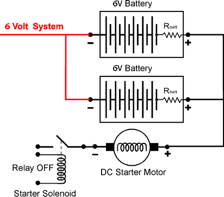
The switch does two things. When the starter is not engaged, the switch places the two batteries in parallel so that the charging system can recharge both batteries at the same time. This connection is shown in the drawing shown below:

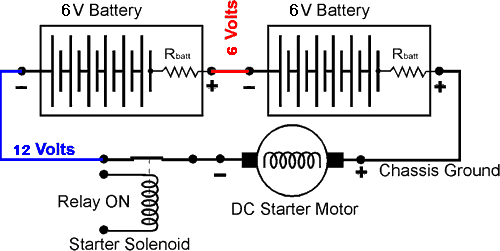
When the starter is engaged, the switch places the two batteries in series for 12 volts cranking power to the starter. This configuration is shown in the diagram below:

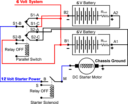
The switch accomplishes this feat using 6 relay contacts as shown in the diagram below. These 6 relay contacts are controlled by the relay coil. When the switch is not active, contacts S1-A and S1-C connects battery B2 post to the 6 volt system. Contacts S2-A and S2-C connects battery A2 post to the vehicle ground. This places the two batteries in parallel and allows the generator/alternator to recharge both batteries.

When the switch is energized, contacts S1-C and S1-B connect B2 to terminal B of the starter solenoid. Contacts S2-C and S2-B connect A2 to B1 which places both batteries in series. Now when the starter solenoid engages, 12 volts is applied to the starter motor.
To troubleshoot this switch, simply check for proper voltages at the six contacts, using the above diagram. You will probably find loose connections or burned and pitted contacts on the relay. Some times you can repair the contacts by dressing them lightly with a small file. The contact material is made of a very soft material so file gently. The contact should be shaped with a slight and rounded bulge in the center of the contact surface.
If the contacts are badly burned or corroded, then you will have to replace the individual contacts or replace the entire relay if individual contacts are not available or if the corrosion is severe.